
It is programmed by ST during production. Using STM32s inbuilt bootloader for secure user-firmware updates.
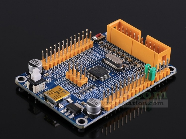
Open103c Standard Stm32 Microcontroller Development Board Kit Blue Development Board Microcontrollers Fiber Board
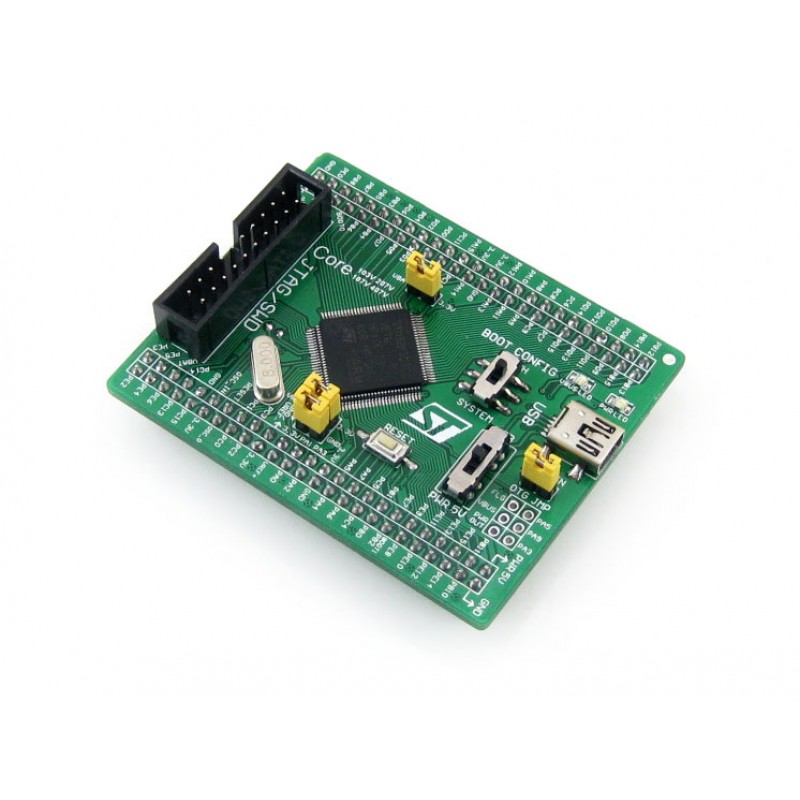
STM32 boot configuration jumpers SW7 SW9 12.
Stm32 application note jtag. This document describes how to connect J-Link to STM32-Discovery boards. AN3364 Migration and compatibility guidelines for. XJTAG provides easy-to-use professional JTAG boundary-scan tools for fast debug test and programming of electronic circuits.
JTAG Interface. These include SWD JTAG and Serial Bootloader. 05-Aug-15 Changed the file name from arm_app_jtagpdf to app_arm_jtagpdf.
J-Link is a JTAG emulator designed for ARM cores. For programming the STM32 there are different possibility that are. This application note outlines the requirements to make the interface compatible with the.
It is connected with a probe cable debug cable to the JTAG connector on the target board. In this project we can choose the language and function and draw the respiratory waveform by the way of random number triggering. Programming and JTAG boundary-scan test instructions in SVF format via the JTAG test access port TAP.
The purpose of this application note is to describe the use of the E-meter PLM demonstration board both in standalone and network mode. This application note describes the USART protocol used in the STM32 microcontroller bootloader. This method requires some basic FPGA development knowledge.
This application note is intended for system designers who require an overview of the. Introduction The debugger communicates with the target processor via JTAG interface. There are a number of methods to upload a binary image of Mecrisp-Stellaris to a STM32 MCU.
The IAP driver can be used to. See STM Application note cd00167594 for your MCU. SWD is ARM specification useful for developing a FW it use only 2 pins SWDIO and SWCLK GND VCC RST pin and optionally SWO pin.
STM32 F2 and F4 series 2. If this is your first time and youre in a hurry checkout the Quickstart page. Jack97 on November 16 2012 060414 pm Quote from.
Jack97 on November 16 2012 034709 pm How must I type the target for STM32-103 cfg. Its main task is to download the application program to the internal Flash memory through one of the available serial. Download a binary file bin from an SD card to the internal Flash memory of STM32 microcontrollers upload all the content of the STM32 internal Flash memory into a binary file.
This application note describes a method that can reduce the programming time when the flash device to be programmed is connected to an FPGA. The STM32 must be put in boot mode. JTAG is ARM specification useful for developing a FW.
This can even be done while an application is running hot-attach. STM3210C-EVAL ST evaluation board implementing the complete range of peripherals and features for the STM32F107 Connectivity line devices with Ethernet USB Host and OTG. Not sure about that particular device but on the STM32 Ive been working with recently the bootloader wont work if you have read protection set in the option bytes.
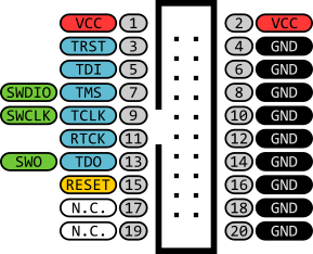
STM32 F4 series only Analog 3x 12-bit ADC Multi-channel 2-channel 2x 12-bit DAC Temperature sensor Up to 1-Mbyte Flash memory Backup data backup SRAM1 Up to 192-Kbyte SRAM OTP bytes1 FSMC SRAMNORNANDCF LCD parallel interface Connectivity. STM32 JTAG 20-pin connector. With System Workbench for Linux Embedded Linux on the STM32MP1 family of MPUs from ST was never as simple to build and maintain even for newcomers in the Linux worldAnd if you install System Workbench for Linux in System Workbench for STM32 you can seamlessly develop and debug asymmetric applications running partly on Linux partly on the Cortex-M4.
J-Link has a built-in 20-pin JTAG connector which can be used to connect to STM32-Discovery boards. Now STM suggest to use the STM32CubePROGRAMMER. To get information about the USART protocol used in the STM32 bootloader refer to the USART protocol used in the STM32 bootloader Application note.
Common Pinouts amt_ann003 v11 Application Note OVERVIEW This Application Note resumes the Common JTAG interface pinouts used by the most popular manufacturers of processors FPGAs or CPLDs devices as ARM Altera Lattice MIPS Xilinx and so more. JTAG SWD connector. Amontec accepts NO responsibility for the accuracy of the.
JTAG_MODE pin configuration 22 iMX RT SJC Security Modes The iMX RT10xx System JTAG Controller SJC supports three different security modes. AN3273 E-meter PLM demonstration board Doc ID 17942 Rev 1 950 11. This application note includes.
When the key is pressed the MCU detects the pressing signal and starts to transmit the waveform data to STVC101WT-01 TFT through the serial port The LCD screen uploads. DFU or DFUSE is STM utility that use USB interface for program the STM32. Application note STM32 microcontroller system memory boot mode Introduction The bootloader is stored in the internal boot ROM memory system memory of STM32 devices.
Two examples are provided as a guide using Altera and Xilinx parts showing how this can be implemented in each case. STMicroelectronics STM32 JTAG Mass ISP Programming Application Note DC04019 NanoPlex general description NanoPlex NPS-06-01-04A Universal Relay ISP-Channel Multiplier allows the expansion of the number of channels of ISP-Programming tools while also offering galvanic isolation. The timing for these TAP signals is shown in Figure 8 page 12.
If you dont set read protection then of course anyone can read out your firmware through the JTAG or SWD. Here we want to make a project for the medical ventilator STONE touch screen STM32. It details each supported command.
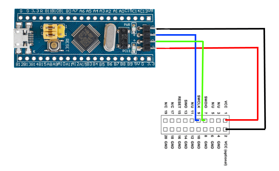
JTAGSW debugETM1 Floating point unit FPU2 STM32 block diagram Notes. The 20 pin JTAG cable has to be connected to J3 of the MBHP_CORE_STM32 module. AN0062 - Application Note Introduction This document explains how to access the debug interface of the EFM32 and how to use this interface to program devices load applications into flash.
JTAG enabled is the default mode of operation for SJC. With OpenOCD a platform independent open source tool is available to access the STM32. The yellow signal are necessary for SWD.
It also explains how to lock and unlock debug access to the MCU to protect the contents of the internal flash and SRAM. JTAGSWD interface using the chosen development toolchain or with the factory-embedded bootloader in the System memory area. STM32 Value Line Discovery is an ultra-low-cost and convenient starter platform the STM32 Discovery Kit is particularly suited to the STM32 Value Line microcontrollers.
Since the SVF format is ASCII and has larger memory requirements it is inefficient for embedded applications. The total number of switched signals is 28. The user can select the Secure JTAG mode by programing a value 0x1 to the eFuse labeled JTAG_SMODE described in Table 2.
It connects via USB to a PC run-ning Microsoft Windows 2000 Windows XP Windows 2003 Windows Vista or Win-dows 7. For more information about the USART hardware resources and requirements for your device bootloader please refer to the STM32 system memory boot mode application note AN2606. 51 SWJ debug port serial wire and JTAG.
The products work with industry standard IEEE 1149x technology which is embedded in many chips. Related documents Available.
How To Debug An Stm32 With An Arduino Project And Gdb
Mini Stm32f030c8t6 Development Board Ttl Gpio Arm Stm32 For Jtag Swd Minimal System Board

Jtag Swd Debugging Via Black Magic Probe On An Stm32 Blue Pill And Blinking A Led Using Stm32cubemx Libopencm3 And Bare Metal C Blog
Jtag Pins
Guide Connecting Your Debugger Stm32 Base Project

Stm32 Core Board Core746i Designed For Stm32f746igt6 With Full Io Expander 1024kb Flash Onboard 64m Bit Sdram Interface Core Design
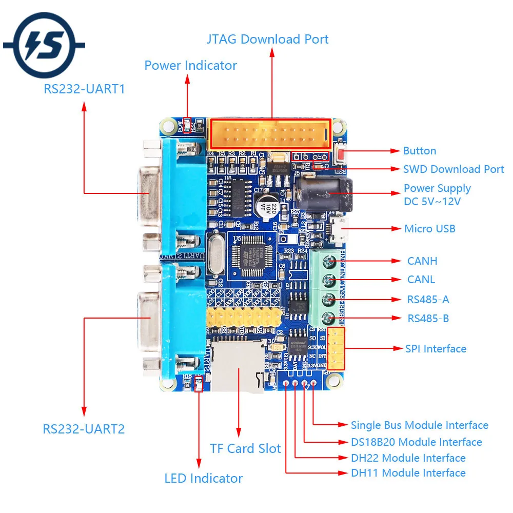
Stm32f103c8t6 Development Board 2bit Rs485 Rs232 Uart Can Protocol Converter Arm Stm32 For Jtag Swd Integrated Circuits Aliexpress
Stm32 Cortex M3 Development Board Core103v