This application note shows a universal approach for programming external flash memory connected to an STM32 microcontroller device with Keil MDK. This application note provides a basic overview of STM32 devices SPI capabilities while highlighting potential issues when handling SPI communications.

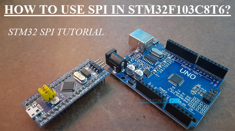
How To Use Spi In Stm32f103c8t6 Stm32 Spi Tutorial Stm32 Spi Tutorial
The STM32 SPI interface provides two main functions supporting either the SPI protocol or the I2S audio protocol.

Stm32 application note spi. Similarly by using which values of series resistor of TX and RX UART will consume low power. Figure 3 shows the recommended electrical connections for 4-wire SPI mode. It describes some typical use cases to use the QSPI interface based on some software examples from the STM32Cube firmware package and from the STM32F7 Series application notes.
It is programmed by ST during production. BTW the application note from STM on software SPI is AN4678. Note that the SDO pin can be disconnected when using 3-wire SPI mode.
SD library SPI pins remap. The design flow follows concepts introduced in application note AN_240 FT800 From the Ground Up. It is possible to switch the interface from SPI to I2S by software.
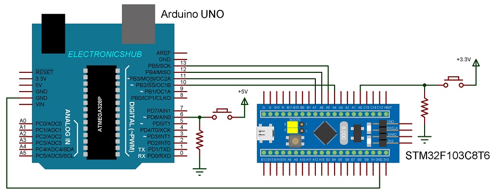
IDE to create Application for HOST eg. STM32 HAL FreeRTOS Part V. Two Potentiometers are also connected with STM32 PA0 and Arduino A0 to determine the sending values 0 to 255 from master to slave and slave to master by varying the potentiometer.
The target application demonstrates the use of the standard STM32ARM libraries to initialize and display different elements on the LCD of the VM800C development system. Note that for STM32 parts the shared data line for half-duplex communication should be connected to the SDO or MOSI pin. In the application notes there is a section called Startup sequence.
The whole system is designed on 33 V. An example is presented using the STM32F769I-Discovery board with an STM32F769NIH6 microcontroller and MX25L51245G NOR flash connected over quad-SPI. The first is to enable the X Y and Z axis which is on by default as well as to set the ODR to 100Hz all in the CTRL_REG4.
AN3273 E-meter PLM demonstration board Doc ID 17942 Rev 1 950 11. AN4760 application note describes the QSPI interface on the STM32 microcontrollers and explains how to use the module to configure program and read external QSPI memories. In this application note code samples are provided for UART0 SPI and I2C-bus.
Describes how to run SAPI throughput application using RS9116W EVK in WiSeConnect mode connected to an STM32 Host MCU board using the SPI interface. There are multiple ways of magic happening. My project use the standard arduino SD library to readwrite data but the default SPI pins PA4-PA7 are used for other purpose.
1 clock and 1 bidirectional data wire. STM32 JTAG 20-pin connector. Any hardware changes required to use SPI in low power mode.
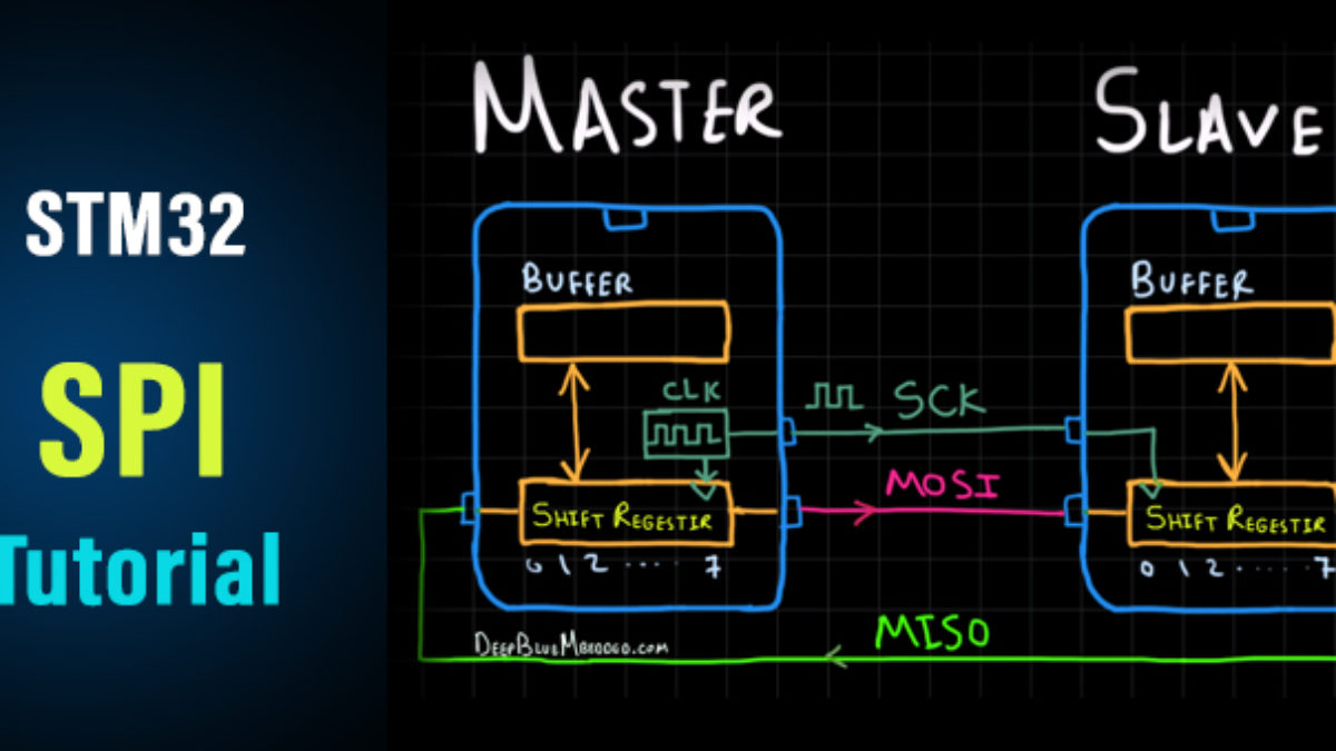
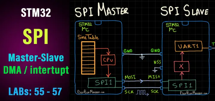
SPI with DMA The main flow of SPI or any other communications for that matter is such that a CPU generates data to send passes it along to the peripheral or bit-banging logic but thats out of scope and then waits for magic to happen. SPI is a bus which means you can. Application note STM32F10xxx SPI application examples Introduction This application note is intended to provide practical application examples of the STM32F10xxx SPI peripheral use.
Its main task is to download the application program to the internal Flash memory through one of the available serial. Application note STM32 microcontroller system memory boot mode Introduction The bootloader is stored in the internal boot ROM memory system memory of STM32 devices. For detailed description on the peripheral please refer to the User manual of the respective.
Table 21 Chip Mode and Device Functions After opening the device with FT_Open developers need to initialize the FT4222H device as either SPI master SPI slave I2C master or I2C slave. 0 Page 3 of 8 ELECTRICAL CONNECTION ADXL345 communication is done via either I2C or SPI 3- or 4-wire mode. Any Logic analyzer for analyzing the data lines eg.
They did it with an F4 but should work on any MCU. This application note describes the Quad-SPI interface on the STM32 microcontrollers and explains how to use the module to configure program and read external Quad-SPI memories. In this STM32 SPI Example we will use Arduino UNO as Slave and STM32F103C8 as Master with Two 16X2 LCD display attached to each other separately.
E-meter PLM demonstration board. It describes some typical use cases to use the Quad-SPI interface based on some software examples from the STM32Cube firmware package and from the STM32F7 Series application notes. SPI Serial peripheral interface OOP Object oriented programming.
RS9116W Throughput Application Note Author. It describes some typical use cases to use Quad-SPI interface based on some software examples from the STM32Cube firmware package and from the STM32F7 application notes. ODR is the data rate selection.
FT4222H works as SPI master. The main difference is that they do single bit but may give you some ideas to speed up yours with DMA and a timer for clock generation. The STM32 SPI Hardware is capable of operating in half-duplex mode in 2 configurations.
1 clock and 1 data wire receive-only or transmit-only Check the target MCUs datasheet for more information about each configuration of them if youre going to use this Half-Duplex mode. I use a Generic STM32F103C8T6 to do a project. The SPI has a wide range of possible configurations which increase the potential for trouble related to specific handling or settings applied to the configuration.
MCUHost with SPI interface. STM32 LIS3DSH Accelerometer SPI. Application Note AN-1077 Rev.
However the demonstrated concepts can be similarly. STM32 boot configuration jumpers SW7 SW9. Is there any documents or application note could explain this bus communication with micro controller including hardware configuration.
It can be one of SPI master SPI slave I2C master or I2C slave device. This document its associated firmware and other such application notes are. This application note describes the Quad-SPI interface on the STM32 devices and explains how to use the module to configure program and read external Quad-SPI memory.
Blocking mode - CPU. Silicon Labs EVK with power cable. It seems that there is another set of SPI pins PA15PB3-PB5 that can be used but I cant found any information how to use it instead of the.
This application note provides code samples which will enable the user to get a jump-start into using some of the serial communication interfaces of the LPC2000 family. The serial peripheral interface SPI allows half full-duplex synchronous. Figure 4 shows the recommended electrical connection for I2C.
SPI Header Recommended to use the cable length not more than 2 inches 4. 21 STM32 SPI Hardware Overview. By default it is the SPI function that is selected.
Bootloader for STM32 with SPI Once the system memory boot mode is entered and the STM32 microcontroller has been configured for more details refer to your STM32 system memory boot mode application note the bootloader code begins to scan the SPI_MOSI line pin waiting to detect a synchronization byte on the bus 0x5A.

How To Receive Spi Data With Stm32 Dma Interrupt Polling Modes

How To Use Spi In Stm32f103c8t6 Stm32 Spi Tutorial Stm32 Spi Tutorial

Stm32 Spi Tutorial Hal Code Examples Interrupt Dma Deepblue

Getting Started With Stm32 How To Use Spi

Using The Spi Interface On Stm32 Devices Visualgdb Tutorials

How To Use Spi With Stm32 Controllerstech
Getting Started With Stm32 How To Use Spi
Getting Started With Stm32 How To Use Spi